
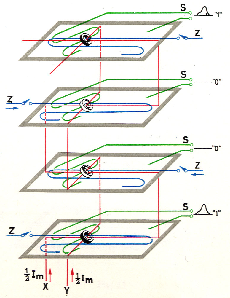
remembered that the S-wire passes diagonally through every ring core of a matrix plane. A separate S-wire is provided for every plane.
Fig. 12 again shows a set of four matrix planes with their associated wires, and a selected stack of four core elements, one on each plane, magnetised in the sequence 1, 0, 0, 1 representing the symbol 9.
The process of reading-out is based upon the fact that, just as suitable current pulses applied via the X- and Y- wires can change the magnetisation of a core, so a change in the magnetisation of that core produces an electrical pulse in the S-wire threaded through that core. To read out a figure, therefore, current pulses corresponding to a field of -JH are passed through both the X-wires and the Y-wires of the selected stack. All cores are thus subjected to a field of (-JH) + (-1H) = -H. Those cores which were originally in the 1 condition therefore immediately change to the 0 condition, and in so doing induce electrical pulses in the S-wire of the corresponding matrix plane. Those cores which are already in the 0 con- however, change their magnetisation only slightly, and thus produce only a small electrical pulse.
Once the stored information is read out in this way, that information is lost, that is to say it no longer remains in the memory. However, the electronic equipment can he so designed that as the information is read out it is immediately written back and stored afresh, so that it is once more available for further operations.