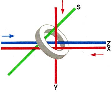
The arrow-heads drawn parallel to the X- and Y-wires indicate what we will consider as the '+' direction for currents flowing in these wires. In operation, only current pulses corresponding to a field of either +1H or -1/2 H are allowed to flow in the X- and Y-wires. If, therefore, the ring core is in the condition +Br, it will change to the -B, condition only if current pulses, each of which corresponding to a magnetising field of- 1/2 H are sent simultaneouly through both the X-wire and the Y-wire. Similarly, if the ring core is in the condition -B,. it will change to the +Br condition only if current pulses corresponding to a total magnetic field of +H are sent simultaneously through the X- and the Y-wires.
It should be mentioned in passing that, just as currents passed through the X- and Y-wires can change the direction of the magnetisation of the ring, so does a change in the magnetisation of the ring produce an electrical force, termed an 'electro-motive force', in the S-wire, capable of causing a current pulse to flow in that wire. It is this effect which is employed to 'read out' or recall the information stored in the memory.
The functions of the Z- and S-wires will be described more fully in a later section of this tutorial.